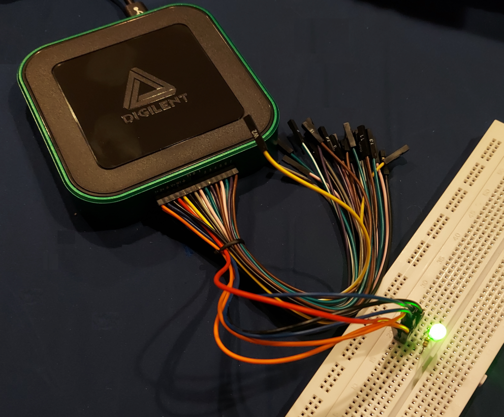
In conjunction with a recent KEEN engineering workshop, I was provided with a complimentary Analog Discovery 3 kit by Digilent. Although I already have a reasonably functional electronics lab at home, the AD3 nonetheless is an intriguing tool to have in the go box, building lots of useful functionality into a single USB-C device.
The idea behind the AD3 is that hobbyists, students, engineers, and experimenters can put together a huge variety of electronics experiments without having to have tons of equipment. One more-or-less pocket-size box can do it all — two programmable DC power supplies; two oscilloscopes not tied to Ground unless you want them to be; two waveform generators, sixteen digital I/O which can be used as a multi-channel logic analyzer / protocol analyzer, and a neat Waveforms software package that ties it all together into a virtual instrument suite. If that’s not enough, there’s a scripting mode where you can control various functions based on the data returned from others.
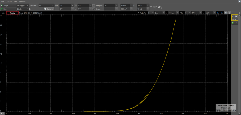
As part of the KEEN workshop, we were given “mystery circuits” and tasked with using the AD3 to investigate what components they contained. Even without the purpose-made component adapter, it’s straightforward enough to connect the device under test (DUT) and a series resistor, and wire the experiment up so the AD3 can provide controlled voltages to the circuit while monitoring the current through the resistor (and therefore through the DUT). After a little experimentation, we determined that the device was a red LED in series with a resistance of a few hundred ohms. (There’s even an I-V curve tracer function that makes this easy.)
Setup of the AD3 is straightforward; a breakout connector is provided to turn the onboard 30-pin connector into thirty female DuPont connector wires. (Long male-to-male pins are provided to facilitate breadboard connections.) Perhaps it was a quirk of the device I got, but inserting the breakout connector took significantly more force than I was initially willing to risk, until the workshop instructors told me they had a spare on hand, should it break. After using a ridiculous amount of force (I estimate 30-50 lbs or so), the connector seated, and fortunately, subsequent uses of the connector don’t seem to require any additional Feats of Strength.
If this hadn’t been provided for free, I’d still be impressed, but perhaps not enough to justify the $379US price tag, given that I already have discrete devices that can do most or all of what the AD3 does, if not nearly as easily. The AD3 does have all of the basic electronics lab functionality you need, but is necessarily limited in terms of power supply voltages and currents, and oscilloscope / waveform generator bandwidth. When testing the self-resonance of capacitors, the Waveforms software started to notify of bandwidth limitations when testing at 20-25MHz. While this is plenty for a basic electronics lab, even inexpensive microcontrollers like the ESP32 run at much higher speeds (240MHz) these days.
Digilent has always had a student-centric focus, though, and with a healthy student discount, the AD3 could make a great personal starter lab. With departmental funds, it’s also a great way to put together interesting, useful electronics experiments for a university or college curriculum.
It’s absolutely going in my electronics go bag, provided I have a laptop along to run it.